If you’ve been stewing in the world of engineering for a little while, you’ll have likely come face-to-face with a lot of cool contraptions and mechanisms. And I think it’s fair to say that occasionally some just feel unfair. Too good to be true. They’re smooth-talking, mesmerising, efficient, capable for their size, loved by everyone – they’ve got it all. A bit like David Beckham in the 00s.
Well, today, I want to talk about another: planetary gears (or epicyclic gears).
If you’ve ever taken apart a cordless drill, ‘popped the hood’ on an automatic transmission, serviced a gear hub or even re-built a gearbox, you’ll have likely seen them. And they’re nothing short of astronomical – if you’ll pardon the pun.
So, buckle up because we’re off to space. It’s time to explore the workings of these wonders.
What are planetary gears?
Let’s start simple. A planetary gear system is a gear arrangement where multiple gears rotate a central gear, and all are enclosed within an internal gear ring. As you’ve probably gathered, the name comes from the similarity to planets orbiting a sun.
A basic planetary gear set includes four components:
- Sun gear – this is the central gear, and usually the input, sending power to the other gears.
- Planet gears – these are several identical gears (typically three). They mesh with the sun and the ring and orbit around the sun gear while also spinning on their axes.
- Ring gear (annulus) – A circular gear with internal teeth that mesh with the planet gears. It may be fixed or used as input/output depending on the configuration.
- Carrier (arm or cage) – This holds the planets at fixed spacing and typically serves as the output shaft.

This arrangement is coaxial, meaning the input and the output can share the same centreline – a major advantage over typical spur gear sets.
And what’s more, their configuration can change, so each type of gear can serve different purposes (within limitations, of course). This is one of the key benefits of planetary gear systems. Let’s look a bit closer…
How planetary gears work
Each gear can serve a different role depending on which component is:
- The input
- The output, or
- Held stationary
This creates multiple possible outputs (including reduction, overdrive and reverse) from a single mechanical system – compared to just two with normal gear trains.
Usually speaking, the sun is the input, the ring is fixed, and the carrier is the output. This process produces speed reduction and torque amplification – kind of the hallmark of planetary gearboxes.
This happens because the planet gears must rotate and orbit simultaneously, so their motion slows the output while increasing torque.

What’s more, epicyclic gear systems have other important features:
Torque distribution
Unlike simple spur gears, where the load passes through one tooth pair at a time, planetary systems engage multiple teeth simultaneously (all around the system). Now, the load is shared between more teeth/gears, there’s less local stress, higher overall torque capability and a lower chance of catastrophic failure. Teamwork in space – to the finest degree.
Floating behaviour
Additionally, most planetary sets allow the planet gears to “float” slightly, which helps them self-equalise loads even with imperfect tolerances – something simple gear pairs cannot do. It’s the proverbial wiggle room we sometimes need in high-pressure situations.
Why do people choose planetary gear systems?
Planetary, or epicyclic, gear systems offer several performance advantages that spur gear systems simply can’t match. Let’s look at some of them.
High power density
Planetary drives can transmit huge torque in a compact package. Multiple planets share the load, so you can safely push more power through a smaller gearbox.
High efficiency
Because torque is shared and sliding friction is reduced (unlike worm gears), planetary gearboxes regularly reach 95%+ mechanical efficiency.
Compact, coaxial design
The sun, planets, carrier, and ring form a concentric stack, eliminating the need for offset shafts. This makes them ideal for applications like:
- Robots
- Drills
- CNC machines
- Automotive transmissions
- E-bike motors
High reduction ratios in one stage
Single-stage reductions of 3:1 to 10:1 are easily achievable. Multi-stage planetary systems can reach 100:1, 200:1, or even 1000:1 without becoming me over the festive season: bulky.
Low backlash
Because multiple teeth are engaged at all times, planetary gearboxes naturally achieve lower backlash (the “play” between gears before they engage) – important for precision robotics and CNC applications.
Shock load resistance
Load distribution and symmetry make planetary gears more tolerant of sudden torque spikes. Again, a bit of safety wiggle room for the real world.
But it’s not all sunshine and rainbows…
Disadvantages of planetary gears
They’re powerful, but not perfect – much to my dismay. Here’s why:
Complex design and high manufacturing costs
Accurate alignment and tight tolerances are still essential – despite the wiggle room available. Because they’re generally used for fancier applications, they usually require fancier materials (and these aren’t cheap).
Difficult assembly and maintenance
The nested structure makes it harder to reach internal components. Great for space saving, not so great for looking after.
Bearing stress
The sun gear sees high radial loads from multiple planets meshing simultaneously. Poor bearing selection can lead to more wear or imbalance. So pick wisely.
Potential for uneven load sharing
Again, the wiggle room is a small safety net. It isn’t a means of accepting low standards forever. If machining tolerances are off, one planet may bear more load than others, causing premature failure – and then see ‘maintenance’ above.
Heat dissipation limitations
Compactness means less surface area for cooling – a serious consideration in high-speed applications.
Overdrive from a galaxy far, far away (i.e., planetary gear ratios explained)
As I mentioned before, you can achieve different outputs based on the configuration. For some of the more important configurations, let’s look at how to calculate their ratios.
Note: there are some great animations here that demonstrate the configurations.
Setup 1: Fixed gear ring → Speed reduction and torque multiplication (most common)
- Input = sun
- Output = carrier
- Fixed = ring
The sun spins the planets, the planets walk round the fixed ring and the carrier turns slower than the sun. As a result, the speed reduces, torque increases, and the rotation stays the same.
Ratio:

Example:
The sun gear has 12 teeth and the ring gear has 48 teeth.
The gear ratio = 1 + 48 / 12 => 5
Setup 2: Fixed carrier (‘Star’ configuration) → Speed increase (overdrive) and reverse direction
- Input = sun
- Output = ring
- Fixed = carrier
Here, the sun spins the planets but the carrier can’t move. The planets force the ring to spin faster than the sun. Because the internal mesh flips direction, the output reverses. This means that the output has a higher speed than the input, the torque lowers and rotation is in the opposite direction.
Ratio:

Example:
The ring gear has 40 teeth and the sun gear has 10 teeth.
The gear ratio = – (40 / 10) => – 4
Setup 3: Fixed sun gear → Mild reduction
- Input = ring
- Output = carrier
- Fixed = sun
The ring drives the planets, the sun stays still, and the planets walk around the sun and carry the carrier with them. So, there’s a slight ratio reduction (depending on tooth counts), a slight torque increase and the same rotation direction.
Ratio:

Example:
The sun gear has 12 teeth, the ring gear has 48 teeth.
The ratio = 1 + 12 / 48 = 1.25
Multi-stage systems
Stacking planetary stages multiplies their ratios, just like we looked at here. For example:
Stage 1 (4:1) x Stage 2 (4:1) = 16:1 total
This is why drills, robots, and e-bike motors use planetary gearboxes… you get huge torque without bulky external gear trains.
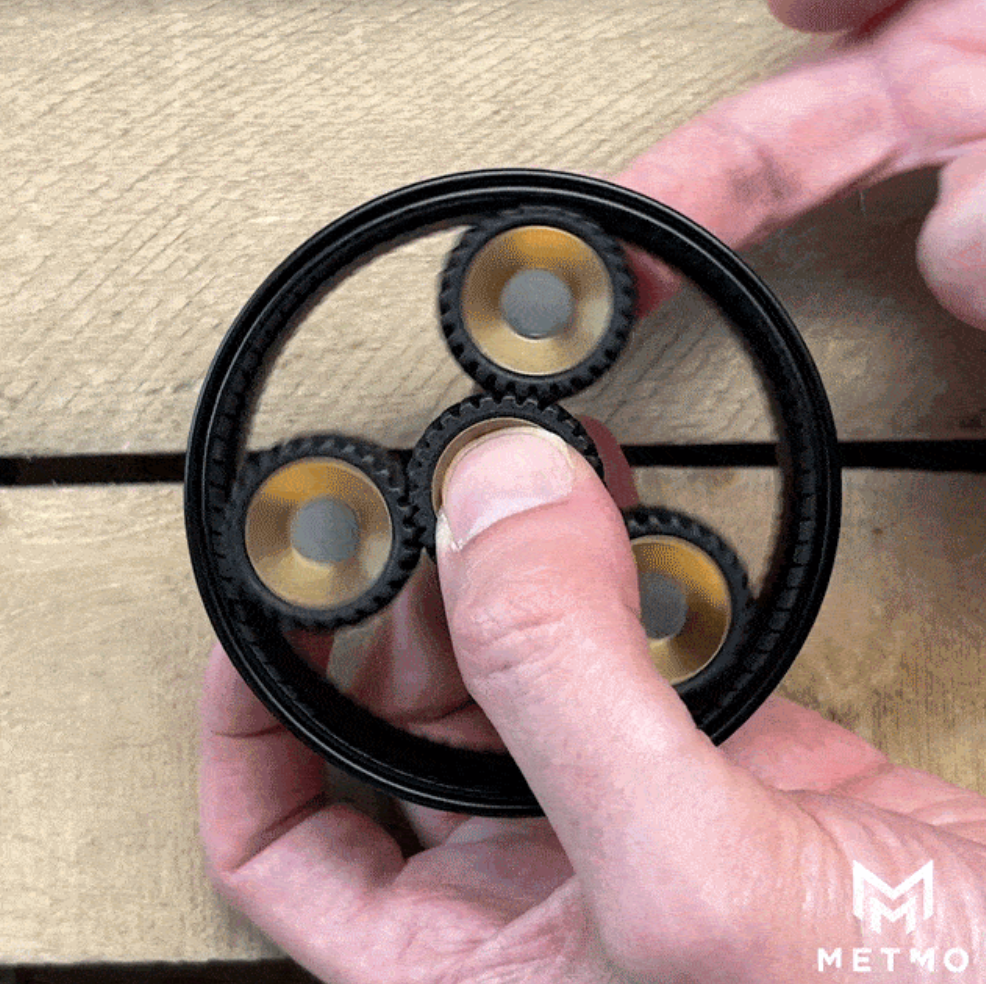
If you’d like to see a 3D printed example – try this.
Where are planetary gears used?
Planetary gear systems appear anywhere compact, high-torque, high-efficiency transmission is needed. For example:
- Automotive transmissions. These rely on 3-4 planetary sets, combined with brakes and clutches, to produce multiple forward gears and reverse.
- Electric vehicles and hybrids. Hybrid transmissions use planetary sets for power-split CVTs, smoothly blending engine and motor power. (A topic for another day, maybe)
- Power tools. Battery drills typically use 3-stage planetary gear reductions, producing up to 150x torque multiplication.
- Robotics and automation. They pair beautifully with servo motors, stepper motors, harmonic drives and industrial actuators. They offer precision, torque and low backlash.
- Aerospace and defence. Planetary systems are used in satellite actuators, solar array drives, and Mars rovers.
- Wind turbines. Planet gears in turbine gearboxes can weigh hundreds of kilograms. Much more than a gust of wind will move.
- Bicycles. 3-speed, 7-speed and 11-speed internal hubs use multi-stage epicyclic trains. They also allow shifting while stationary, which is impossible for derailleurs.
- Consumer electronics. Vacuum robots, printers, gimbals, and even smart-home devices rely on planetary reduction for quiet, smooth torque.
So, as you can see, planetary gear systems are everywhere, in all sizes. Now, let’s have a look and see where they came from.
History of planetary gears
The story of planetary gears blends ancient astronomy, steam power, early automobiles and modern robotics. It goes a little like this:
Ancient circles on circles
The earliest planetary-like systems appear in Greek astronomical models. Some 2000+ years ago. In particular, Ptolemy’s epicycles (for explaining the motion of planets) and the Antikythera mechanism, an analog computer using nested gears to model planetary motion.
Granted, they’re not gearboxes, but they follow the same principle of circles moving on circles. And like every invention ever, they’re a stepping stone to what came next.
Steam power sparks a gear revolution
For a few thousand years, developments were quiet (or there’s no record). But in 1781, James Watt patented the Sun & Planet mechanism – made by his employee William Murdoch – for his steam engines. It converted a reciprocating motion into rotary motion while dodging crankshaft patents of the time. This was arguably the first mechanically useful planetary configuration.
From horsepower to planet-power
Then, they entered mainstream engineering. Wilson-Pilcher automobiles used planetary sets in early transmissions. The Ford Model T (1908) used a 2-speed planetary gearbox. And Oldsmobile’s 1937 Automatic Safety Transmission used planetary gears and is a direct ancestor of modern automatics.
A design too good to replace
As with a lot of developments, when materials, machining and analysis improve, so do outputs. Now, planetary gear systems are the backbone of lots of uses – as we saw earlier. And I’m sure they’re only going to get better.
How to avoid your planets falling out of orbit
Now, you might be tempted to go and make your own planetary gears - for models, robotics or 3D printing, or just fits and giggles. (If you do, make sure you share it with us on Reddit, or CubeClub). So, it might be handy to know some of the usual weaknesses and failure points so you can maybe avoid them yourself.
Failure 1: Stripped sun gears
This is often the smallest and fragile gear. It needs strong materials and proper lubrication.
Failure 2: Misaligned carriers
Even slight misalignment causes uneven tooth engagement. Use rigid carriers and accurate tolerances.
Failure 3: Planet gears binding
This is when the planet gear gets stuck (instead of rotating freely). It occurs when centre distances aren’t precise enough or planets vary in diameter. Floating carriers can help.
Failure 4: Poor lubrication
This applies to most gearboxes of most materials. If you’re 3D printing yours, keep in mind dry plastic gearboxes seize quickly, so use lithium grease or PTFE-safe lubricants to help.
Failure 5: Wrong material choices
PLA planets will deform over time. Use nylon, polycarbonate (or metal) for more durability.
Failure 6: Heat build-up
This is especially common in multi-stage 3D printed systems. Ventilation or short duty cycles help.
Failure 7: Incorrect tooth counts
The ring gear tooth count must equal the following – if not, the mesh won’t assemble.

Hopefully, they’ll help you avoid some of the trial and error.
Stellar reputation: deserved
Planetary gears are wonderful, aren’t they? They’re one of those mechanisms that truly keep the planets in line. And they’ve proven themselves over two millennia.
So whether you’re a model maker, hobby engineer, a professional engineer, robotics enthusiast or just someone who loves beautifully engineered mechanisms, I’m confident a deeper understanding of planetary gears will help you find a new appreciation for the weird and wonderful contraptions around you. Maybe it’ll even inspire you to make some of those contraptions yourself.
Here’s a little planetary gear we made once for our beloved Helico.

I hope you’ve enjoyed reading. Again, if you happen to make your own planetary gear system, we’d love to see it. Pop it in our Subreddit or CubeClub forum, and show us what you’ve made. Or anything you’ve made for that matter. Until next time!


Share:
A Gripping Story
Release The Fractal