We thought it would be interesting for you all if we took a bit of a tour of the production process that will be used to make the final drivers. In the past we have always shown the making of the prototypes, but what happens after that is often a bit of a mystery. Partly because our suppliers don’t like us going around with cameras and partly because getting a camera into a machine is not the easiest of processes.
While making the second round of prototypes for Pocket Driver, we were able to persuade someone to put their camera inside one of the machines while it was running, so we can give you all a glimpse of what goes on in full scale production.
For this post we'll be diving into the milling of the handle. This is one of the more complex pieces to produce and so there are lots of juicy details below. We will be continuing to try and capture more of the processes while we are in production, but for now, I hope you find the following information interesting!
As well as showing each operation used in the making of the handle, we have also given a description of what is actually going on in each process so you get an idea of the method behind the madness. Anyone that’s a pro-machinist will notice early on that the cutting fluid is not often on target; that was intentional so we could film it and see what was going on.
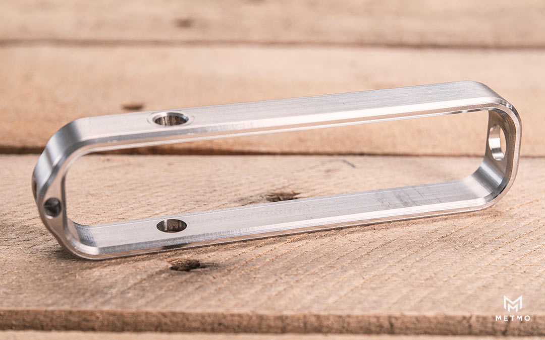
So, let's get stuck into the milling of the handle from a billet of solid 2024 aluminium on a 5 axis CNC Milling Machine!
Op 1 - Cutting the outer profile
The first thing that is done is the milling of the outer profile. You can see in the opening sequences that the tool is automatically loaded into the spindle from a tool changer; these are pre-loaded into the machine to match the number and sequence of operations - for op 1 it's an end mill.
The machine cuts the outside profile near to its final dimensions, taking a bigger rough cut initially, followed by finer ones later on. That means the cutter moves less as it cuts and so gives a more accurate and finer finish on the subsequent cuts. Using the same end mill, the cutter plunges down to the correct depth and then repeats the same rough cuts to create the hole in the centre of the handle. This one feels like a lot is going on, because in this machine the part that is clamped moves around whilst the milling bit only moves up and down so when they move at the same time you get this optical effect. The second small operation is to put a centre point in for the next drilling operation, so that the next drill goes in at exactly the right point. This is a drilling operation that plunges down using the previous centre point as a guide. It's generally done like this as the end of a longer drill like this one can wander when getting started, which can then cause inaccuracy and breakage of the drill. A centre point stops that from happening.
The big spinny thing (as dubbed by the guys in the office) is otherwise known as a face or shell mill. This is a specialist tool that has a number of cutters mounted around the edge that can be individually replaced. This operation flattens and finishes the top surface of the handle so we can retain the machined surface as the final finish on this part. It also creates a flat square surface as a reference point for later on.
This exciting operation involves the joining and opening up of the two holes that become the paracord connection point. It is also the part that breaks the most drills at the moment! When working on aluminium we can cut the metal quite fast, but cuts on steel have to be done much slower so as not to break things.
The last milling process takes place on the outside and inside surfaces of the handle. A milling cutter is used to make a very light cut just to bring the sizes down to exactly the desired dimensions. By making a light cut, the cutter will deflect less over the depth of the cut so the tolerance is maintained all the way down the part. This also reduces vibration and gives a much nicer looking and smooth finish.
This one is really satisfying to watch! In milling and turning, there is just something about putting a chamfer on that says 'this part is finished!'. Chamfer is the technical term for turning a 90 degree edge to a 45 degree angle. This process forms both the inside and outside edges of the handle, giving it a nicer feel in your hand.
This is where the 5 axis machines really start to show off. To get the part into this position, the machine will turn the part by 90 degrees to allow for the milling of the through hole on the end, using a couple of milling cutters. One is used to remove material and the second to finish the surface. It is milled in this circular fashion to achieve an optimum cut. The milling is easier for a straight cut direction, but for a curved hole like this, the cutter needs to move in a clockwise direction, so the part needs to move against it in the opposite direction to achieve the right cut.; Whilst not captured on film here, the same operation was repeated on both sides of the part. This is the first manual operation in the process so far. The freshly machined part is taken out and put into a nylon clamping block and clamped into place. The nylon clamping blocks are used to protect the outer finish of the part. The back of the handle is then machined, removing the material that the part was previously held on with. This op reveals, for the first time, the handle at its final dimensions. You can see that the removal of the centre of the handle has been left till last; this is mostly so that it can still be clamped securely, without any risk of it being damaged by the machine or moving from where it's clamped and damaging the machine.; The return of the shell mill! Here we machine the final finish of the back surface and, because the part is pressed flat to the vice against the top surface that was machined earlier, this operation ensures that the top and bottom are parallel (as long as the operator has put it in right that is!). Round two of the chamfering process is done over a couple of cuts. A small cut is taken each time to reduce the vibration and give a smooth final finish to the handle. The final cut on the inside uses the centre point of the chamfering tool to perfectly cut through the last piece in the centre of the handle, leaving just enough so that it doesn’t fall out on its own. The final piece is complete. As it lifts, the waste material in the centre can be seen falling out. The last stages to this aluminium version are the bead blasting of the part to remove any machining marks and sharp edges, then the hard anodising that is done by a different supplier. There it is, post-finishing, in all its glory! This is a different process to the one we used to make the bigger Driver. Originally that handle was formed out of a sheet of stainless steel and given an element of human interaction, which allowed for some slight variances in the finished pieces. By using a CNC (computer numerical control) machine for the Pocket Driver, the parts cost more but the repeatability and reliability is the same every time. When you see all of the processes that go into making a part like this and the time it takes to make just a single component, you can really start to appreciate why CNC machining costs what it does! The machines that are used to make the other parts are all similar to this, using CNC ;machines to turn our digital designs into reality! I hope you've found this update useful and interesting. As always, if you guys have any questions about any of this, just let me know and I will be happy to help answer them. From our update about the Magnetic Bit Case, we had a few people leave us some comments to request that we 'make the two products connect together in a neater way'. We are looking into how best to do this, but at the moment the best option would be to have an additional part that could attach by a magnet and let a case and a driver nest together perfectly in parallel. We are going to continue working on this and will have something for you guys to look at in a few weeks, but, for now we are still happy to take suggestions from you and see whether this is something you are interested in us making for you. An alternative could be to make an open-source design that you can make and modify yourself; we're also very open to this.Op 2 - Milling out the inner profile
Op 3 - Drilling the through hole
Op 4 - Big spinny thing (face mill) to finish the top surface
Op 5 - Opening out the through hole
Op 6 - Finishing the inner/outer profiles
Op 7 - Inner/outer chamfer
Op 8 - Flip over and drill the through hole
Op 9 - Mill the back side material off
Op 10 - Face mill back side
Op 11 - Back side chamfers
Op 12 - Blast off and remove
Op 13 - Marvel at its shine!

In Other News


Share:
A Case For Your Bits
It's Time to Pick a Pocket Pack!